
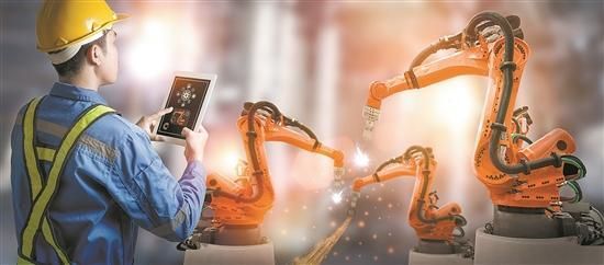
In recent years, thanks to the rapid development of the industrial robot market, linear motion control industry has entered a stage of rapid development. The further release of downstream demand has also driven the rapid development of the upstream, including linear guides, ball screws, racks and pinions, hydraulic (pneumatic) cylinders, gears, reducers and other transmission core components. There is also a trend of substantial increase in orders. The entire operation and control industry market is showing a vigorous development attitude.
The driving source of industrial robots drives the movement or rotation of joints through transmission components, so as to realize the movement of the fuselage, arms and wrists. Therefore, the transmission part is an important part of the industrial robot.
The linear transmission mechanism commonly used in industrial robots can be directly generated by cylinders or hydraulic cylinders and pistons, or it can be converted from rotational motion by using transmission components such as racks and pinions, ball screw nuts, etc.
1. Moving Joint Guide Rail
Moving the joint guide rail during the movement can play a role in ensuring positional accuracy and guidance.
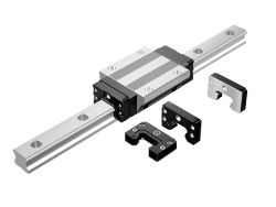
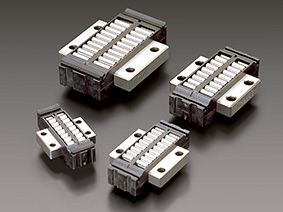
There are five types of moving joint guide rails: ordinary sliding guide rails, hydraulic dynamic pressure sliding guide rails, hydraulic hydrostatic sliding guide rails, air bearing guide rails and rolling guide rails.
At present,the fifth type of rolling guide is most widely used in industrial robots. As shown in the diagram below, the inclusive rolling guideway is constructed with a support seat that can be easily attached to any flat surface. At this point, the sleeve must be opened. It is embedded in the slider, which not only enhances the rigidity but also facilitates the connection with other components.
2. Rack and Pinion Device
In the rack and pinion device, if the rack is fixed, when the gear rotates, the gear shaft and the carriage move linearly along the direction of the rack. In this way, the rotational motion of the gear is converted into the linear motion of the carriage. The carriage is supported by guide rods or guide rails, and the hysteresis of this device is relatively large.
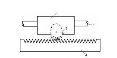
1-Drag Plates;2-Guide Bars;3-Gears;4-Racks
3. Ball Screw and Nut
Ball screws are often used in industrial robots because of their low friction and fast motion response.
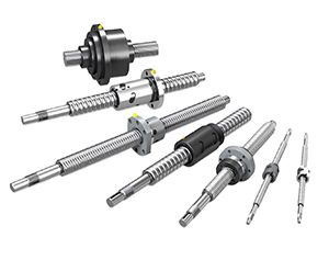
Since many balls are placed in the spiral groove of the ball screw nut, the screw is subjected to rolling friction during the transmission process, and the friction force is small, so the transmission efficiency is high, and the crawling phenomenon during low-speed motion can be eliminated at the same time; When applying a certain pre-tightening force, the hysteresis can be eliminated.
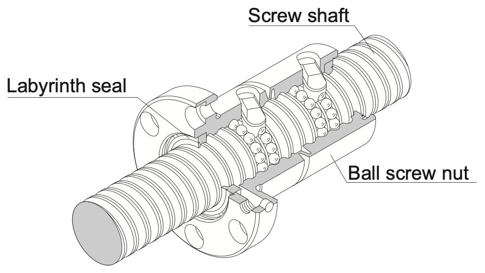
The balls in the ball screw nut pass through the ground guide groove to transmit motion and power back and forth, and the transmission efficiency of the ball screw can reach 90%.
4.Liquid (Air) Cylinder
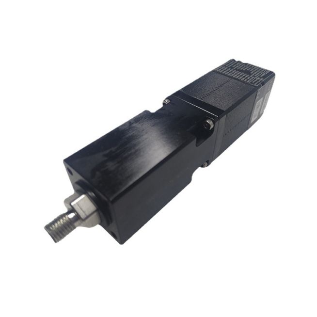
KGG Miniature Electric Cylinder Actuators Stepper Motor Actuators
The hydraulic (pneumatic) cylinder is an actuator that converts the pressure energy output by the hydraulic pump (air compressor) into mechanical energy and performs linear reciprocating motion. Using a hydraulic (pneumatic) cylinder can easily achieve linear motion. The hydraulic (pneumatic) cylinder is mainly composed of cylinder barrel, cylinder head, piston, piston rod and sealing device. The piston and cylinder adopt precise sliding fit, and the pressure oil (compressed air) enters from one end of the hydraulic (pneumatic) cylinder. , to push the piston to the other end of the hydraulic (pneumatic) cylinder to achieve linear motion. The movement direction and speed of the hydraulic (air) cylinder can be controlled by adjusting the flow direction and flow of hydraulic oil (compressed air) entering the hydraulic (air) cylinder.
Post time: Feb-01-2023


